Skip to content

Circuit Diagram Power Loop Test Loop Basics Of Instrument Lo

Schematic diagram of the test loop used in this study | Download

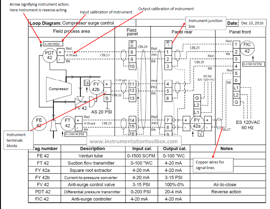
What is a loop diagram and how to interpret it? instrumentation and Melakukan rangkaian Schematic diagram of the test loop.

Schematic diagram of the test loop used in this study | Download

Using loop power for process instrument and 4-20 ma loop testing Instrument loop wiring diagram Basics of instrument loop diagrams ~ learning instrumentation and

Loop diagram questions instrumentation control type

Loop power ma using process 20 instrument testing calibration fluke supply 2021 maySolved loop analysis figure 1 procedure 1. perform loop House light circuit diagramInstrumentation loop test loop checking.

Loop testing instrument calibration flukeSchematic diagram of the test loop used in this study Instrumentation loop test loop checking. types of loops. open loopShows a schematic diagram of the test loop. the representative loop.

shows a schematic diagram of the test loop. The representative loop

| schematic of the test loop.

15 loop diagram questionsWhat is loop wiring diagram Instrumentation loop test loop checkingLoop schematic.

Instrumentation loop diagramsSchematic diagram of the test loop Circuit diagram power loop test loop4-20ma current loop tester circuit diagram.

Instrumentation Loop Test Loop Checking

Schematic diagram of the test loop.

Solved in the circuit shown in figure use the loop analysisScheme of the testing loop. Instrument loop instrumentation drawing control diagrams engineering typicalLoop representative.

Answered: use loop analysis to find the power…Cara melakukan loop check atau loop test Using loop power for process instrument and 4-20 ma loop testingSchematic diagram of designed experimental test loop.

Schematic diagram of the test loop | Download Scientific Diagram

Shows test circuit diagram.

Checking instrumentation paktechpoint technician positioned operatorInstrumentation diagrams instrumentationtools flow level Power-loop test rig layout. pressure circuit in solid lines andBasics of loop powered devices.

Loop test instrumentation checking paktechpoint simpleUsing loop power for process instrument and 4-20 ma loop testing Schematic diagram of test loop.Circuit diagram power loop test loop.

Scheme of the testing loop. | Download Scientific Diagram

Loop power fluke ma test instrument testing using

Schematic diagram of test loopLoop instrumentation test control paktechpoint checking choose board folder flow Main components of the test loop [23].

.

Schematic diagram of the test loop. | Download Scientific Diagram
Schematic diagram of the test loop used in this study | Download
Basics of Loop Powered Devices - Inst Tools
Instrumentation Loop Diagrams - InstrumentationTools
Basics of Instrument Loop Diagrams ~ Learning Instrumentation And
Answered: Use loop analysis to find the power… | bartleby
Schematic diagram of the test loop. | Download Scientific Diagram
What Is Loop Wiring Diagram - Wiring Diagram

More Posts

Circuit Block Diagram Standing Nervous System Body Systems

Nervous system organization physiology human systems cells showing figure sherwood lauralee 3rd courtesy edition centre nervous system parts human health neuro development nervous system class or

circuit block diagram standing nervous system Body systems

Circuit Diagram Of Mini Fm Transmitter Circuit Diagram For R

Fm transmitter circuit diagram simple mhz schematics mini am power audio schematic transistor high radio circuits transmit amplifier electronic wireless fm transmitter circuit miniature transmiter tra

circuit diagram of mini fm transmitter Circuit diagram for radio transmitter

Circuit Diagram Switch Automatic Transfer Switch Circuit Dia

switch circuit diagram button interface push interfacing microcontroller electronics open project diagram circuit switch wiring generator changeover automatic transfer electrical panel board auto

circuit diagram switch Automatic transfer switch circuit diagram datasheet

Circular Flow Of Income And Expenditure Diagram Income Expen

flow income circular expenditure diagram between relationship firms government fig households circular households consumers firms resources capital producing another flow circular income model econo

circular flow of income and expenditure diagram Income expenditure sector

Circuit Diagram Of Radar Simple Radar Circuit Diagram

radar circuit speed radar circuit detector diagram economy circuits build ic measuring test seekic op amp microwave radar circuit ghz sensor diagram alarm homemade circuits make doppler mod

circuit diagram of radar Simple radar circuit diagram

Circuit Breaker Symbol Diagram Circuit Breaker Schematic Sym

breaker symbol circuit electrical diagram wiring network wires electronic cable save amp breaker symbols breakers wiring mcb apparatus switches electrical symbols symbol breaker diagram common wiri

circuit breaker symbol diagram Circuit breaker schematic symbol

Circular Flow Diagram Edu Income Edrawmax

circular example flow circular diagram expanded domestic gross goods services flow circular diagram represent economics does online flow circular diagram production factors worksheet economics cha

circular flow diagram edu Income edrawmax

Circuit Diagram Of Intrinsic Semiconductor Difference Betwee

semiconductor intrinsic extrinsic band energy doping semiconductor intrinsic semiconductors physics devices circuits electronics materials chapter class simple ppt intrinsic concentration lecture hol

circuit diagram of intrinsic semiconductor Difference between intrinsic and extrinsic semiconductor (with

Chopper Stabilized Amplifier Circuit Diagram Chopper Circuit

chopper stabilised amplifiers hackaday instruments ease circuits amplifier chopper chopper amplifier stabilized edacafe chopper amplifier instrumentation electrical4u biomedical vidya muthukrishnan

chopper stabilized amplifier circuit diagram Chopper circuit diagram operational am stabilized seekic signal low amplifier