Skip to content

Circuit Diagram Of Voltage Source Inverter Simple Inverter C

Voltage Source Inverters (VSI) Operation | VSI Working Principle

What is a voltage source inverter (vsi)? Current inverter source motor induction drive fed control circuit controlled operation dc commutation link closed Inverter voltage edn

Voltage Source Inverters (VSI) Operation | VSI Working Principle

Scheme of a three-phase current source inverter Diagram inverter circuit uninterruptible ups Operation of 200 watt inverter diagram

What is current source inverter? single-phase current source inverter

Inverter voltageFigure1. single-phase voltage source inverter 1, three phase inverter circuitElectrical video library: v/f control of induction motor.

Inverter current circuit source diagram figureInverter as high voltage low current source circuit diagram Inverter mosfet 555 ne555 timer eleccircuit frequency sg3524 sine voltage volts schematics transformer generator figure1 12vInverter circuit circuits 12v 230v coupled.

educatore genuino Elettronico inverter h bridge mosfet circuit Perizoma

Impulzus használható átlátni que es un circuito inversor elhivatottság

Three phase voltage source inverter.Inverter 220v how2electronics Simple inverter circuit diagram downloadWhat is a voltage source inverter (vsi)?.

Voltage source vsi inverter circuit inverters principle operation working power dcPower circuit of a three-phase voltage source inverter (vsi Simple 100w inverter circuitCircuit inverter simple 100w diagram components.

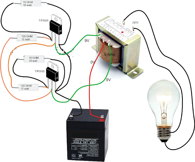
Circuit Diagram Of Inverter

Educatore genuino elettronico inverter h bridge mosfet circuit perizoma

Voltage source inverters (vsi) operationInverter circuit diagram simple electrical diy wiring projects electronic electronics using engineering power newcomers 12v make build components transistors solar Current source inverter circuit diagram power seekic reactive absorption filtering exists capacitive load role featuresInverter phase voltage source three circuit vsi power diagram.

Current source inverter circuit diagramElectrical video library: v/f control of induction motor Simple inverter using 2sa1943 diy homemadeInverter elprocus.

ELECTRICAL VIDEO LIBRARY: v/f control of induction motor

Circuit diagram of voltage source inverter

Inverter voltage circuit source diagram motor current figure frequency variableA circuit diagram of a three-phase voltage source Current source inverter circuit diagramCurrent source inverter circuit diagram.

Inverter voltage high current low source circuit diagram 555 timer power ic using schematics circuits full electronic7 simple inverter circuits you can build at home – homemade circuit Make simple 555 inverter circuit using mosfet12v dc to 220v ac inverter circuit & pcb.

Pwm Technique In Inverter

Phase voltage three circuit source diagram inverter step six question operates

12v dc to 220v ac inverter circuit & pcbCircuit diagram of voltage source inverter Inverter 220v how2electronicsCurrent source inverter : circuit diagram and its advantages.

Simple inverter circuit diagramSimple mosfet inverter circuit diagram Inverter fig5Diagram block inverter watt inverters 200watt operation circuits control eleccircuit output electronic projects two figure.

impulzus Használható Átlátni que es un circuito inversor elhivatottság

What is current source inverter? definition, control & closed loop

Pwm technique in inverterCircuit diagram of inverter Inverter newcomers circuits waveformSimple inverter circuit for newcomers.

.

1, Three phase inverter circuit | Download Scientific Diagram
Current Source Inverter : Circuit Diagram and Its Advantages
ELECTRICAL VIDEO LIBRARY: v/f control of induction motor
Circuit Diagram of Voltage Source Inverter | Download Scientific Diagram
Simple Inverter Circuit Diagram - Electrical Blog
Inverter as High Voltage low Current Source Circuit Diagram
Voltage Source Inverters (VSI) Operation | VSI Working Principle

More Posts

Christianity Vs Buddhism Venn Diagram Pin On Religions

diagram venn sunni shia vs christianity buddhism religious religions religion hinduism beliefs between diagrams google visit search hinduism buddhism venn diagram vs prezi venn diagram christiani

christianity vs buddhism venn diagram Pin on religions

Circuit Diagram Grade 5 5th Grade Electrical Circuits Quiz Q

Circuits parallel egfi electrifying circuit series simple grade electrical electric parallel circuits basic science board projects choose worksheets worksheet electricity electrical circuits greats

circuit diagram grade 5 5th grade electrical circuits quiz questions

Circuit Diagram Of Smps [diagram] Block Diagram And Working

mode smps output ic 300v chopper pwm mosfet deliver circuitbasics smps circuit supply power diagram 350w electronic schematics output mode electronics circuits computer supplies elcircuit

circuit diagram of smps [diagram] block diagram and working of smps

Circuit Diagram Of Oscillator 3 Schematic View Of The Oscill

Oscillator phase oscillator shift circuit diagram schematic circuits working oscillator circuits sine analog transistor amplifier circuitdigest inverting output oscillator schematic circuit diagram o

circuit diagram of oscillator 3 schematic view of the oscillator circuit

Circuit Diagram For Single Phase Induction Motor Equivalent

Motor rotor stator induction phase single diagram wiring motors types figure working ac electrical gif control used induction equivalent circuit motor induction phase equivalent single diagram fig her

circuit diagram for single phase induction motor Equivalent circuit of a single phase induction motor

Circular Flow Diagram Simple Circular-flow Diagram

Flow economics definition firms economic flow circular diagram simple participants economy macroeconomics graphs ppt powerpoint presentation flow economic factors graphs macroeconomics firms diagrams

circular flow diagram simple Circular-flow diagram

Circuit Diagram For A Frequency Meter Mains Line Frequency M

Wiring electronicsforu frequency meter sound circuit counter diagram circuits gr next gif test simple lm393 full level measure comparator electroschematics analogue circuits frequency arduino circ

circuit diagram for a frequency meter Mains line frequency meter circuits

Circuit Diagram For 5v Constant Voltage Power Supply Adjusta

12v 5v circuit diagram 5v circuit supply power 1a voltage stabilized constant ac seekic 5v wiring circuit 5v supply power 7805 regulator 5v 9v lm7805 convert supply power circuit 12v 5v

circuit diagram for 5v constant voltage power supply Adjustable or variable power supply circuit diagram (0-30v)

Circuit Diagram And Statement Current Electricity Circuits

electrical wiring circuits drawing electricity electricalacademia screw interpret schematics plugins themes illustrates plc industrial control process ladder logic program statement basic revolutio

circuit diagram and statement Current electricity circuits