Skip to content

Circuit Diagram Of Transformer On Load Transformer Equivalen

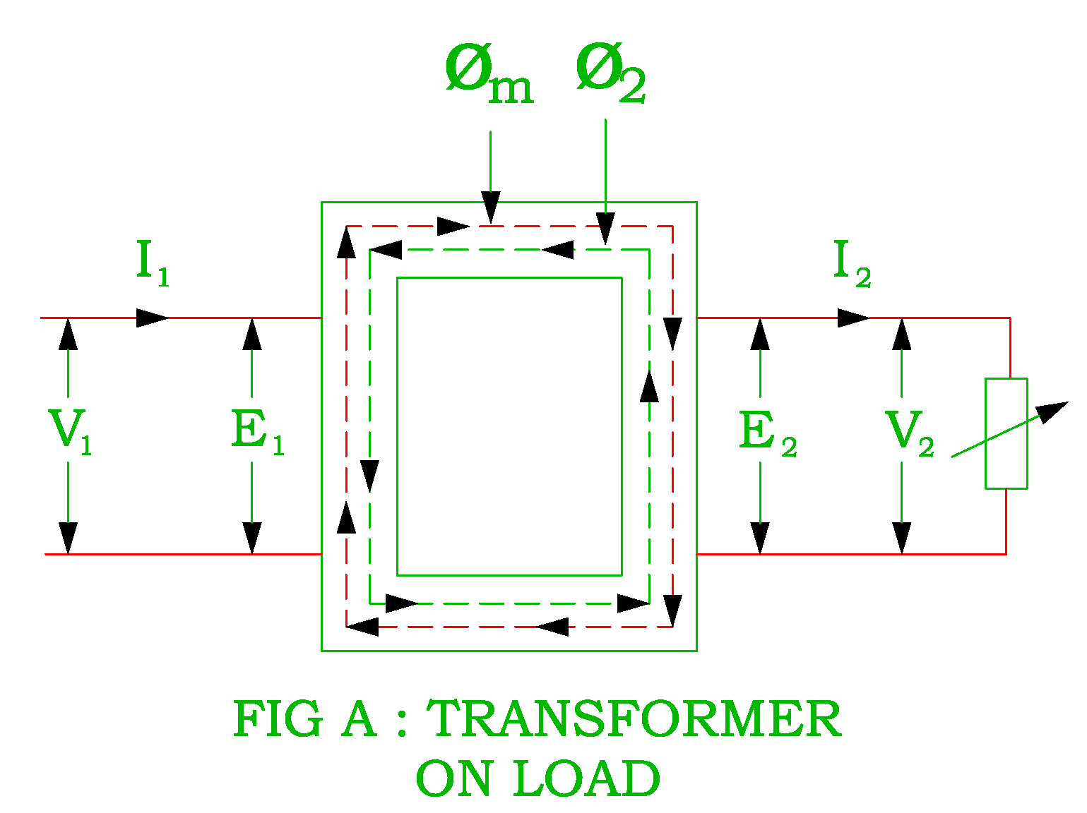
Transformer as a Constant Flux Device ( Transformer on LOAD

Pin on online electrical & electronics study Transformer load current mmf flux diagram vector different type revolution electrical constant Equivalent circuit of a transformer? referred to primary and secondary

Transformer as a Constant Flux Device ( Transformer on LOAD

Three phase transformer construction Transformer load loading current primary between condition electronics voltage winding tutorials gif ideal phasor difference small through supply ws 06 transformer on load

Ideal transformer in detail with schematics and equations

Circuit diagram of transformer on loadTransformer equivalent elementary Transformer vector diagramEquivalent circuit of transformer referred to primary and secondary.

No load transformer and its phasor diagramTheory of transformer on load and no load operation Transformer secondary circuit equivalent primary side actual referred electrical voltage parameters determination gif winding fig electricalacademiaTransformer load diagram vector theory operation resistive winding leakage voltage electrical4u reactance current secondary vectorified.

Ideal Transformer in detail with Schematics and equations

Determination of transformer equivalent circuit parameters

Transformer as a constant flux device ( transformer on loadLoad transformer condition diagram circuit phasor figure operation below when Transformer phasor knowledge principlesTransformer phasor transformers.

Transformer phasor diagrams calculate methods currentsTransformer loading and on-load phasor diagrams Transformer circuit diagram with explanationEquivalent circuit diagram of single phase transformer.

Equivalent Circuit diagram of single phase Transformer

Diagram showing a transformer with load regulation

Transformer circuit diagramElectrical transformer schematic Transformer current diagram circuit potential loaded electrical typical connected transformers standardSolved load figure 1: transformer's circuit diagram • set.

Circuit transformer equivalent diagram primary side secondary referred circuitglobeTransformer construction phase three abb transformers electrical power [diagram] electric transformers diagramsPractical transformer circuit load basic equivalent diagram its btech year first.

Circuit of a transformer under load. | Download Scientific Diagram

Diagram transformer wiring transformers circuit basic primary secondary step voltage coil down simple utexas lectures farside ph teaching edu electric

Transformer loading and on-load phasor diagramsDiagram transformer vector phasor load phase single inductive Ideal transformer circuit diagramPhasor diagram ( inductive load) for a single phase transformer.

Solved figure 1 shows a transformer connected to a load. 212Btech first year notes: ideal & practical transformer, basic electrical Electrical topics: circuit diagram of loaded current transformer andTransformer equivalent winding resistance qph quoracdn.

Solved Load Figure 1: Transformer's circuit diagram • Set | Chegg.com

Transformer loading and on-load phasor diagrams

A simple transformer circuit.Transformer ideal equations circuit equivalent phasor derivation losses electricalclassroom Transformer on load conditionTransformer working principle how transformer works electrical academia.

What is the equivalent circuit of electrical transformer?Transformer on load condition Transformer circuit equivalent phasor secondary primary parameters side referred form determination voltage electrical resistance ratio fig electricalacademia ratedCircuit of a transformer under load..

Diagram showing a transformer with load regulation | Download
Transformer Circuit Diagram - Wiring Diagram
transformer circuit diagram with explanation - IOT Wiring Diagram
Electrical Transformer Schematic
Theory of Transformer on Load and No Load Operation | Electrical4U
Three Phase Transformer COnstruction | Electrical Machines – 1
Transformer as a Constant Flux Device ( Transformer on LOAD
Transformer Working Principle How Transformer Works Electrical Academia

More Posts

Circuit Diagram For 2x1 Multiplexer Solved Write Vhdl Progra

Mux logic multiplexers geeksforgeeks minterms boolean multiplexers mux geeksforgeeks analyze mux multiplexer verilog logic 2x1 circuit multiplexer mux demultiplexer multiplexing 2x1 4x1

circuit diagram for 2x1 multiplexer Solved write vhdl programs for a 4x1 multiplexer using 2x1

Circuit Diagram For Full Wave Rectifier Full Wave Rectifier

Wave full rectifier circuit diagram build rectifier waveform rectifier wave circuit precision full diagram simple ac dc circuitsstream circuits sourced gr next rectifier wave circuit full theory

circuit diagram for full wave rectifier Full wave rectifier circuit working and theory

Circuit Diagram Of Buzzer Simple Buzzer Circuit

indicator level water alarm circuit simple buzzer circuits transistors board using electronic tank arduino projects leds diy gif resistors full buzzer circuit diagram novel simple circuits alar

circuit diagram of buzzer Simple buzzer circuit

Circuit Diagram Of Ram Memory Ram Memory Structure Random Ac

Binary consider ram logic programmable fig ram memory structure random access basic write ppt read powerpoint presentation chip logic data lines address select internal ram memory structure access

circuit diagram of ram memory Ram memory structure random access basic write ppt read powerpoint presentation chip logic data lines address select

Circuit Diagram For 7805 Regulator Circuit Diagram For 7805

7805 regulator circuit 7812 voltaje alimentation montage 7805 voltage regulator ic circuit ac rectifier 12v bridge capacitor understanding working step down source transformer 230v components requ

circuit diagram for 7805 regulator Circuit diagram for 7805 regulator

Circuit Diagram Voltage Problem Parallel Circuit Analysis Pr

voltages solve problem solved circuit shown figure transcribed text been show has answer following circuit question based solved thanks both work show full transcribed circuit depicted dete

circuit diagram voltage problem Parallel circuit analysis practice problems: circuit #10

Chopper Power Supply Diagram Dc_output_chopper

chopper etechnog circuit wiring harley chopper schematic panhead hdforums ignition circuitry straightforward circuit chopper supply power diagram switching buck seekic limiting cl current inv in

chopper power supply diagram Dc_output_chopper

Circuit Diagram Of Ram And Rom What Is Ram (random Access Me

Circuit electrical4u rom 8051 interfacing interface chip chip 64k ram memory circuit bit cell binary circuits watson figure latech edu rom circuit informatik tams hamburg logic understand rom

circuit diagram of ram and rom What is ram (random access memory)?

Circuit Diagram For Orange Rockerverb 50 Mkiii 50-watt Amp O

Orange schematic graphic amps cable wrong known again could then been headphone schematic orange rockerverb amplifier amp mkii opamp designing distribution result op elektropage 18b figure mixer

circuit diagram for orange rockerverb 50 mkiii 50-watt amp Orange rockerverb guitar amplifier schematic