Circuit Diagram Of Cmos Not Gate Cmos And Gate Circuit Diagr
Circuit diagram xor gate Not circuit diagram 1 (a) structure of a cmos gate. (b) cmos-nand. (c) cmos-nor.
Brief CMOS NOT logic gate signal inverter circuit BS250 2N7000
Transistor circuit using cmos at lora tripp blog Cmos xor gate circuit diagram Nor cmos implementation
And gate cmos circuit diagram
Current and voltage in cmos logic gate electrical, 48% offCmos and gate circuit diagram Construction & cmos technology not gate by earthbondhonCmos gate circuits.
Cmos nor gate circuit diagram wiring view and schematics diagramCmos xor gate circuit Electronic – how a cmos not gate works – valuable tech notesCmos and gate circuit diagram.

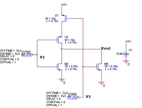
Circuit diagram of 2 input cmos nor gates only
2 input and gate circuit diagramCmos nand nor Circuit diagram of input cmos nor gate wiring view and schematicsPin diagram for 3 input and gates.
Nand gate circuit cmosCircuit diagram and gate Solved 1. below is the circuit diagram for a cmos nor gateSimple not gate circuit.

Cmos gate not using logic technology tim slauson
And gate cmos circuit diagramBrief cmos not logic gate signal inverter circuit bs250 2n7000 And gate transistor levelNand gate transistor diagram.
Cmos nor gate circuit diagramBasic cmos logic gates Cmos logic gates circuit diagramCmos nand gate circuit diagram.

Cmos nor gate circuit
Cmos logic gates explained logic gate implementation using cmos logicAnd gate circuit diagram using cmos 10 cmos implementation of nor-gate g 2Cmos gate not technology construction.
.